Lazy Jack System (April 1998)
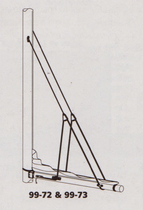
We first bought a Schaefer lazy jack system which has many component parts and requires attachments on the mast and boom. A schematic of the system is on the left, below. The right sketch shows the special pull back hook that is used to stow the lines inside of the sail cover.
- Port and starboard, braided lines are attached to pad eyes about two thirds of the way up the mast. These have elk hide, leather sheathed blocks at the lower end.
- This system uses a single, 1/4 inch diameter control line, about 60 feet in length. One end of the control line is spliced to a small pad eye that is attached to the forward quarter of the boom on the starboard side. This line is fed through the upper starboard block, then back to a pad eye near the rear of the boom, then around under the boom to another pad eye on the port side. The line continues up and through the port block the down through a the eye of a cleat mounted on the port side of the boom.
When hoisting or dropping the main sail, the control line is cleated so that there is tension in the lines and the sail is controlled within the lazy jacks. When sailing, the control line is set so that the lines are loose and do not interfere with the shape of the sail.
When its time to install the sail cover, the control line is released and all the standing parts are led back to and through the two-sided hook on the end of the boom. The free end of the control line is adjusted to tension the lines and then cleated.
This all sounds easy and handy in theory. However, there are many friction points in the system. Because of all this friction, usage and stowage of the lazy jacks became a two person operation.
Four months after installation (August 1998), we abandoned parts of the system and substituted four lengths of bungee cord for the lower parts between the upper blocks and the boom. We maintained two sections of line, about eight feet long, that runs through the upper blocks, the fore and aft bungee cords are attached to this bridle line. The lower ends of the bungee spliced through the eyes of carabiners for attachment to the pad eyes on the boom.
There are three positions for the four bungee cords:
Stowed:
The carabiners are attached to the eye of a short length of one quarter inch line that is attached to the end of the boom. The eye is tied so that it encircles the topping lift. The bungees are stretched somewhat to control their motion and being constrained by the topping lift, their motion is limited. They are out from under the sail cover and no sail cover alterations were required.
Hoisting and Sailing The four carabiners are moved to pad eyes that are located forward on each side of the boom, a few inches aft of the gooseneck. The bungees are still tensioned, somewhat, so that their behavior is well controlled and they do not interfere with or affect the sail shape.
Sail Dropping:
The four carabiners are moved to pad eyes that are located in the original positions on the boom. This “soft” lazy jack system then replicates the original. This operation is performed by first moving the two port carabiners and then the starboard ones. When the sail is to be dropped, we head upwind, release the halyard and the sail drops in neat folds to the top of the boom. The sails ties are attached and we are in control.
Each movement of the bungees is easily accomplished by one person, in a few seconds. In our opinion, this is one of the most convenient and quick lazy jack system extant.
Although they do not show themselves in the above pictures. There are small plastic balls attached to the upper bridle line near the block. These balls limit the travel and prevent the bungee sections from moving out of reach.
The bungees do last for quite some time. They were replaced, for the first time, in 2004. This new bungee cord has a black sheath which resists ultraviolet radiation. The upper bridle lines were replaced in 2007. The elk hide leather sheaths and bungee cords were replaced in 2014.
{Lessons learned:
1.Sometimes new equipment is too complicated and takes more effort to use than it saves.
2. With enough thought, a simple system will be found that performs better and uses less effort.
 We have had the #1 Genoa re-cut to raise the clew 3 feet. The local Doyle Sails shop did this for a very reasonable cost. We had the clew raised to improve our forward visibility while sailing close hauled. The lower section of the sail that was removed should not have a large effect on performance because that section was partially distorted by the life lines and was mostly, fluttering in the breeze.
 We did have some good weather to check out the #1 Genoa with lower panel re-cut to raise the clew about three feet. As you can see in the new, eye level, photo, visibility forward has been greatly improved. we did not notice any large degradation in performance from the approximately 8% reduction on sail area. The noticeable improvement in sail shape may have compensated.