Showing posts with label Cabin. Show all posts

Saturday, June 27, 2015

The Taming of The Stairs


For many years, we have struggled with the stair unit. When in place, and locked in position, it functions well and is a safe and convenient means of transit between the cockpit and the cabin. However, when engine access is needed, it must be removed and it becomes a heavy, unstable and unmanageable piece of hardware with no easy means of storage. It is best stowed by laying the unit on the cabin sole where it occupies a large amount of space.

We pondered various solutions for stowage of the stair unit, including hinging the unit at the bridge deck, hoisting it to the overhead and locking it to the overhead. This would prevent access to the outside and would become a hazard to anyone working below the stowed unit. this concept was quickly rejected.

We also considered adding hinges to one side of the unit that would allow it to be opened, like a door, to allow engine access. This would involve providing clearance to allow the unit to rotate. Since only limited space for access would be provided, this idea was also rejected.

We finally got the idea that it would be nice if the unit would stand up on its own and and be stable after it was slid out of it's normal position. This requires a means of support that provides the necessary stability to balance the unit. Many different contraptions were considered before we settled on extensions for the base of the unit.

The assembled extensions are shown in this picture. This photo is taken of the bottom of the stair unit, with the extensions in place. The extensions consist of lengths of one inch, square aluminum tubing with round, adjustable felt pads on each end. The extensions are about ten inched long. They are set in frame work made of mahogany 1X4 stock with supports made from aluminum angle stock. The assembly is attached to the inside of the stair unit with wood screws.

Extension Unit Installed

The next photo shows the stair unit standing, erect, on the cabin sole. For those familiar with the boat and the stairs, this is rare event. For this picture the extension unit was attached with a pair of c-clamps.

Extension unit, standing, temporary mounting

Th extensions provide quite a bit of stability to the stair unit. In fact, a significant heel angle can be accommodated. The next photo shows the tipping-point angle for the stair unit, with the extensions in place.
Unit With Extensions, Tipped


By now, you are wondering where do the extensions go when the the stairs are in normal position.

This photo shows the extension unit, removed from the stairs and placed in the normal position.

Extension Unit In Normal Position

The extensions protrude into the engine compartment, beside the longitudinal bulkheads that support the engine mounts. This photo clearly shows the asymmetry of the opening for the stair unit, The aft ends of the extensions nearly contact the vertical brackets of the engine mounts. This limits the length of the extensions.

The felt pads on the aft ends of the extensions are supported by and slide on supports that we added to the vertical bulkheads. These supports are at the same level as the cabin sole and function as a continuation of the sole. The starboard and port supports are shown in these photos.


Port Support
Starboard Support


A support consists of a 1-1/2 by 1-1/2 square mahogany block that extends from the end of the sole, along the vertical bulkhead, as far as the engine mount bracket. The top surface of the block is at the same level as the lower surface of the plywood sole (3/4 inch below the top surface). The supports are attached to the bulkhead with lag screws. A section of 3/4 inch thick by 1-1/2 wide teak stock is cut to fit and is attached to the top of each support block with a pair of screws that are countersunk to be flush with surface. The provides a smooth, sliding surface for the felt pads that is the same level as the sole.

Since the extension unit has been installed, we find it to be convenient a safe way to manage removal and stowage of the stair unit. The felt feet make sliding of the unit on the sole easy and a pleasure. The advantages for this design are that there are no loose pieces and no tools are required. The unit has added very little weight to the assembly and the cost has been quite low. However, mahogany is not cheap.

Lessons Learned:

1. Don't suffer with things that are difficult to deal with.
2. Keep considering various solutions and select the most effective one. Experiment with it and keep
    it if it works.


Wednesday, April 23, 2014


Re-relocation of the Batteries to Starboard (Nov 2013 - April 2014)

We had noticed for some time that the boat had small “list” to port. We partially corrected this by keeping the fresh water tank nearly full. We attributed most of the list to the fact a majority of the heavier equipment is located to port. This includes the head, holding tank, stove and batteries. We reviewed various options for equipment that might be easily moved from port to starboard as well as fit in the available space on the starboard side. The batteries were found to be the best candidate. There was some under utilized space beneath the starboard cabin settee. We measured the space and found that if we pushed the fresh water tank forward approximately twenty inches, there would be just enough space to accommodate the two batteries. This space is located forward of the galley sink, below the settee cushion bunk board and along the face of the settee facing.


This picture shows the relocated water tank, battery and tool space. There is a new bulkhead between the aft end of the tank and the battery-tool area. The athwartship aluminum stringer, which consists of two angles that are riveted together, is to support the bulkhead as well as the bunk boards.


This next picture is a close up of the finished battery and tool space. This also shows the fore and aft, aluminum stringer that supports the small bulkhead between the battery and tool spaces.


This picture shows the modified bunk boards, before painting. The middle access cover is for the water tank inspection and fill port. The two, aft, access covers are for the battery and tool spaces.


This project did meet the goal of curing the list-to-port. Moving over one hundred pounds of equipment about four feet to starboard did have a significant effect. Also, we gained a tool storage space that moves the tools to starboard at least a foot. We have yet to use the storage space that we gained in the “old” battery compartment.

{Lessons learned: 
  1. Careful measurements and mockups, with full size pieces, like cardboard batteries, save much of the “cut twice” phenomenon.
  2. Take the effort to get exact dimensional data for the parts that you plan to use. We obtained detail drawings from attwood Marine Products, for the battery trays.
  3. We were fortunate in gaining a new spot for the tools that is secure, easy to access and moves the weight to starboard.}


Saturday, June 22, 2002

Settee Overhead Access Panels (June 2002)

These over head panels do not get much attention because we seldom look at them as they are usually below eye level. These panels are removable for access to the wiring harnesses and deck fittings. Removal is usually a rare event. The panels are 3/8 th inch plywood and were originally covered with foam-backed, vinyl fabric. Being 23 years old, they looked their age. We chose to remove the old fabric and laminate light weight, vertical grade Formica to the plywood panels. These photos, taken looking aft, show the results on the starboard and port sides, respectively.


Saturday, April 20, 2002

Relocate Holding Tank and Batteries (Nov-Apr 2001/2)

“A piece of cake”

We had sensed, for a long time, that the boat sailed with its bow down in the water. This was also obvious from the pictures of the boat sailing. This, we deduced, was due to the fine entry of the hull and the location of the holding tank in the v-berth area of the hull. Whenever the holding tank was empty, we could measure a better performance level.

We examined the possible spaces in the boat that could be used to relocate the holding tank to a more rearward location. We found an “under- utilized” space on the port side, aft and below the bunk board and forward of the stove compartment. This space was about half consumed by a too-large battery box. The other half was empty and used to store the hatch boards while we were underway. We carefully measured this space and found that an available holding tank would, probably, fit in this space. This tank, a Kracor, PN 2-73821S, 21 gallon capacity, seemed to be designed to fit this space.


The installation of a tank in this space is dependent upon relocating the two batteries to another location. We found a smaller space, below the stove compartment, with a door, that is large enough to slide a battery through. On the left is a view looking down into the space with the stove compartment removed. This space is adequate for the two batteries. We built a suitable floor and installed two battery trays, with hold down brackets, in his space. We also relocated the battery cables.


On the right is a view looking aft into the new battery compartment. During installation, one battery is slid inside the compartment, clamped in place and the cabling is attached. Then the second battery is slid into its mount, secured and the cabling is attached. Each positive terminal is protected by a red plastic boot. 


Having found a place for the batteries, we carefully studied the space to assure that there is enough space for the chosen holding tank and its fittings. This included making a foam core mockup of the tank, based on the dimensions given by Kracor and fitting it onto the space. With the assurance that it would fit, we ordered the tank.


The space required some modification to accept the tank and its fittings. The fore and aft centerline rib is cut down so that it supports the bottom of the tank and lateral ribs are added for further support. The ribs are bonded to the hull with 3M 5200 adhesive. The forward athwartship rib was cut down to allow insertion of the tank and to clear the fittings on the front of the tank. The inside surface is painted with Interlux Brightside Polyurethane paint.


The bunk board that covers the tank space had been supported by the fore-aft and athwartship hull ribs. To provide this support, a new frame work is built over the tank space. This frame work, constructed of oak is mounted with fasteners so that it can be fitted after the tank is installed. The picture below shows the tank and frame installation. The frame accommodates the tank vent hose, tank access port, tank inlet and drain ports. We did install a Sealand vent filter to satisfy our olfactory receptors.

The space forward of the holding tank is still used for storage. See lower picture. The inlet and drain plumbing, which runs through this space, does not interfere with its use. This space also contains the thru-hull fitting and valve for the head supply water. The inlet pipe continues through the main bulkhead and connects to the hose in the head compartment. The drain, pump out, hose continues forward, past the head compartment to the old fitting in the anchor well because we did not wish to create another hole in the deck. This tank and plumbing have performed well since it was installed. 

Once all the bunk boards are back in place there is no evidence of this major renovation.


All of this effort did cure the bow-down problem and improve performance. We did see the boat sail better to windward and through choppy seas on other points of sail. “Keep the weight out of the ends” is still good advice. Also, we said good bye to the old, stinky tank.


{Lessons learned:
  1. Make sure that you have measured the space correctly and have good dimensions from the supplier.
  2. Make mockup pieces. They are a lot easier to deal with. Measure again.
  3. Take time to dry fit all the pieces before you apply any glue.
  4. Painting the space makes it more pleasing.}

Saturday, July 15, 2000

Rework Electrical Panel (July 2000)

The original electrical panel had the following installed items: the Columbia panel, a stereo radio and a basic 110 Vac panel. In addition, this panel only provided access from the aft side.


We reworked this panel and its mounting system to allow access to the wiring and components by pivoting the panel forward. We made a new plywood substrate, resurfaced with matching laminate. We revised the lengths of and rerouted several wires. We also acquired and installed a new Blue Star, 110 Vac electrical panel with circuit breakers for cabin lighting, battery charger, GFCI outlets and three spare positions. We scrapped the old car stereo installation in favor of a nice boom box. The ammeter was relocated to this panel as part of the engine controls project. Below, on the left. is the view inside the cabin and on the right, the top of the panel is pivoted forward and downward.


{Lessons Learned:
  1. Study features that are shown either at boat shows or in magazines.
  2. Always include features that will make any future maintenance task easier to perform.}

Friday, August 27, 1999

Fresh Water Tank (August 1999)


The fresh water tank story is based on another mystery. At this point in time we had been sailing the boat for about twelve years. Almost every time that we sailed, involving a port tack in a good breeze, we would find fresh water, at most a gallon, in the bilge. We searched, many times, for the source of a leak. The evidence pointed to the starboard side of the boat, at the point of maximum beam. We checked this area of the hull and deck and could not find a source.

For some reason, perhaps to check the water tank, we had removed the bunk board under
the starboard cabin seat cushion. The water tank is directly
underneath this board. We saw that the water tank had damage to the outboard side, mid tank, near the top of the tank. This damage penetrated the tank and made it possible to leak water from inside the tank. We assumed that this damage had occurred before or during the construction of the boat. So, when we were on port tack and heeled, water would leak out and head for the bilge. Mystery solved! Since we did not want to attempt a repair to the polyethylene tank. we searched a found a new Kracor water tank with a capacity of 25.75 gallons that fit the space exactly. (see photo) We acquired and installed this tank. We have been pleased with this tank since 1999 and it has never leaked!

While we were replacing the water tank we thought that the space forward of the tank could be better used if the bunk boards were modified. We cut the bunk board at the bulkhead shown in the picture above and added an athwartship support for the aft section and a new forward section.


We also added support for a small, loose panel for access to the water tank clean out port. The forward section was replaced with a larger, loose panel; with finger hole. The gave much greater access to the forward space. This forward, loose, panel was also supported along its forward edge. The forward space was used to store the tool bag, engine oil containers and spare parts. These boards were painted, in the brown color, after fitting was complete


Thursday, June 18, 1998

Cabin Curtains (June 1998)

The Columbia 8.3, original cabin curtains were attractive. However, they had some unsightly tracks, were difficult to adjust and keep clean (especially liked by spiders). This is a scan from the Couimbia sales brochure.


 We searched for alternatives, including blinds of all types, and found nothing to be satisfactory. We came up with the idea of inserting translucent plastic panels on the inside of the window lites. We obtained some white, translucent, acrylic material 1/8th inch thick and cut out pieces to fit each of the four cabin lites. We added small, teak blocks at the top and bottom of the window frames. The panels are slid between these blocks and the window glazing. The panels are flexible so they easily slip between these blocks and the window glazing.


These pictures show the panels during and after installation. We use a small suction cup, shown in the picture, to pull the panel from the frame so that it can be slid back.

Later, we cut a small slot in the top edge of each panel, a couple of inches forward of the center and
wide enough to clear the block. This allows the panel to be set against the window and reduces the sliding to this dimension.

These panels reduce the sun load, cabin temperature and fading of interior components. They also maintain privacy while docked. If vision is desired, they can be removed in few seconds. For stowage, we keep them between the v-berth cushions and the hull.

Wednesday, April 8, 1992


Gimbaled, Longitudinal Stove Compartment (April 1992)


We had an idea that a two-burner Origo, non-pressurized, alcohol stove. with a gimbal mount would fit in the port side of the galley area. Careful measuring and investigation of the area proved the if we sacrificed one of the galley drawers and about 6 inches of length in the port settee the stove assembly would fit, be accessible and accommodate pots and pans at all heel angles. An appropriate section of the counter top, the cabinet forward face that surrounded the two drawers and the drawer hardware were removed. A small section of the bunk board was cut off and an athwartship beam added to permanently mount it and provide a ledge for the remainder of the bunk board. One of the three drawers was moved to a position above the inboard drawer so that two of the three drawers are still in use. The cut out, drawer rework and the bunk board support are shown below.


The stove compartment, shown below, is basically a box with the gimbals mounted to the fore and aft faces to hold the stove. The box has a cover, which is laminated with Formica that matches the counter top. The cover is stored vertically in slots at the outboard side of the box.When in place the cover very neatly and almost completely closes the stove compartment. The cover. if made larger, would block access to the storage lockers when the stove was in use. (see lower pictures)


The stove compartment is built as an assembly which is installed by sliding it rearward into the cut out area and is then fastened to the trap bulkhead. The rear wall of the compartment is removable to accommodate the fasteners. The stove compartment provided space below the stove shelf, between the former galley bulkhead and forward face of the compartment. We created a rectangular opening in the forward face for a removable panel that snaps into place. This provided what appears to be glove box for small items, including gloves! The picture below shows the compartment in place, before the stove installation. The “glove box” is visible in these shots. A GFCI electrical outlet was relocated to the inboard face of the compartment.


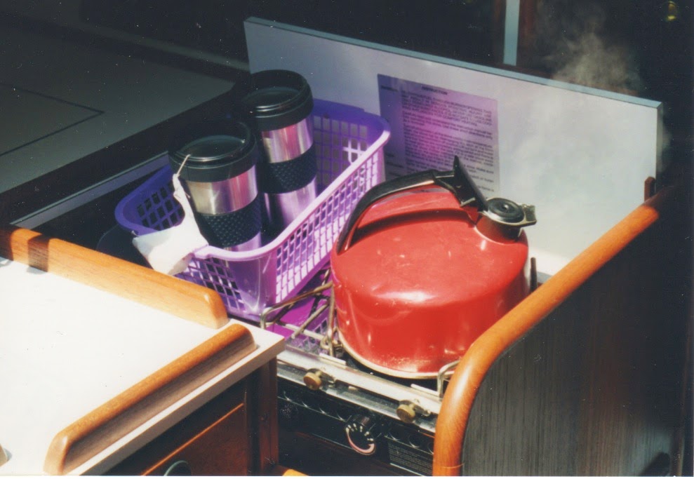
This photo shows the finished installation during use and underway. Time for tea!


{Lessons learned:
1. Athwartship mounted, fixed stoves do not belong on a sail boat.
2. Be willing to sacrifice a little seating space for a functional stove compartment.
  1. Again, Consider the aesthetics and always attempt match the rest of the boat interior. This boat has mahogany stained teak which is very hard to match. We made up a bottle of our own special stain that we named “La Yu Hue” that was used for all of our projects.
  2. Always provide safe stowage of loose items, e.g, the stove cover, so that they do not become dangerous objects when the going gets rough.
5, Do not pass up an opportunity to add useful storage space.}

Tuesday, April 16, 1991


Cup, Bowl and Plate Rack (1991)

The boat lacked any secure stowage for dishes. We obtained  a set of, four each, Heller, plastic cups, dinner plates, salad plates and soup bowls. We designed and constructed a teak rack to securely store these dishes and mounted it on the galley counter just aft of the of the ice box lid. The plates and bowls of this set interlock which helps to retain them in the rack. The left-hand picture shows the rack and general area. The right-hand is a closeup, showing the cutout for cup stowage.


{Lessons learned:
  1. When buying items for a boat, consider the storage requirements.
  2. Also, consider whether the design of the item is compatible with storage requirements.}

Saturday, May 12, 1990

Lockers Added to Cabin (May 1990)


The original cabin had simple shelves behind the settee seat backs and plain foam-backed vinyl covering the hull. (see left photo, below) We felt that this space could be put to good use for the storage of the many small items accumulate on a boat. After much thought and looking at options on many other boats, we sketched a plan for lockers that mount on and to the shelf as well as the forward and aft bulkheads.


We designed and constructed four lockers, one for each end of the shelf on the port and starboard sides. These lockers are about 15 inches tall and 27 inches long. (see right photo) The lockers have sliding plastic doors that match the ones in the galley area. The major challenge to building these lockers was to get them to follow the hull contours. Careful measurements, including the use of tick boards, were essential. Enough space was left between the lockers to provide a book shelf with a lift-out bar to restrain the books when the boat is heeled.


These lockers provide handy and secure storage for many of the items that we carry with us when we go sailing. This picture shows some of the essential coffee and tea items.


The lockers also have an extended trim surrounding the top surface. This provides additional, safe storage for books and small items.

{Lessons learned:
1.Take every opportunity to add valuable storage space in a small boat.
2. Consider all items that need to be securely stowed while sailing.
3. Consider the aesthetics and always attempt to  match the rest of the boat interior.}

Friday, May 27, 1988

Hull model (May 1988)

The model is scaled 1/2 inch to the foot and was shaped from glued up blocks of scrap RenShape 450 (a model making material that is used in the auto industry). We were fortunate that Columbia provided approximate hull lines in their sales brochure. The most difficult part was to get the paint lines straight and fine to within about 1/2 mm (0.02 inches).


The completed model, mounted on a display board, is show below.


This view shows the model and display board, as mounted in the boat on the port side of the forward bulkhead.


(Revised: 25 Jan 2018)

Tuesday, May 10, 1988

Cushion Fabric (May 1988)


Sewed new upholstery fabric covers for all interior cushions. New on left, old, typical, on right.