Thursday, June 18, 1998

Cabin Curtains (June 1998)

The Columbia 8.3, original cabin curtains were attractive. However, they had some unsightly tracks, were difficult to adjust and keep clean (especially liked by spiders). This is a scan from the Couimbia sales brochure.


 We searched for alternatives, including blinds of all types, and found nothing to be satisfactory. We came up with the idea of inserting translucent plastic panels on the inside of the window lites. We obtained some white, translucent, acrylic material 1/8th inch thick and cut out pieces to fit each of the four cabin lites. We added small, teak blocks at the top and bottom of the window frames. The panels are slid between these blocks and the window glazing. The panels are flexible so they easily slip between these blocks and the window glazing.


These pictures show the panels during and after installation. We use a small suction cup, shown in the picture, to pull the panel from the frame so that it can be slid back.

Later, we cut a small slot in the top edge of each panel, a couple of inches forward of the center and
wide enough to clear the block. This allows the panel to be set against the window and reduces the sliding to this dimension.

These panels reduce the sun load, cabin temperature and fading of interior components. They also maintain privacy while docked. If vision is desired, they can be removed in few seconds. For stowage, we keep them between the v-berth cushions and the hull.

Wednesday, May 27, 1998

Fuel Tank (May 1998)

We had a scary night in May when we discovered that the original, steel fuel tank was dripping gasoline into the bilge. Fortunately, we were safe in our boat well. We went and bought some gasoline jugs and pumped the fuel into them from the inlet fitting of the fuel tank. Later, we emptied the jugs into the fuel tank of our vehicle. The fuel tank is located below the cockpit sole in one of the least accessible areas of the boat. We managed to disconnect the fuel and vent lines and the straps that secured to tank. We removed the tank to a safe place and finished draining fuel into the jugs. Most of this effort was completed in the dark of night under the light from a flashlight. We were concerned, properly, that any lights that we turned on might cause a big explosion. We soaked up the remaining fuel in the bilge. We left boat to “air out” for a while, thankful that it had not blown up. The next day, we found that the root cause of the leak was a rusted through weld seam on the end of the fuel tank.

We searched and located, at Boat US, an 18 gallon, rotationally molded, polyethylene fuel tank that fit the available space below the cockpit. This tank has fittings and a fuel gage sender that matched those on the old tank. This made installation a lot simpler. We adapted the mounting area to accept this tank used a set accessory hold-down brackets to retain the tank. Acquisition, Installation and testing of the new tank was completed within 10 days. This picture shows the connections to the new tank.


Wednesday, April 22, 1998

Lazy Jack System (April 1998)

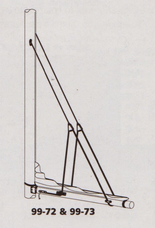
We first bought a Schaefer lazy jack system which has many component parts and requires attachments on the mast and boom. A schematic of the system is on the left, below. The right sketch shows the special pull back hook that is used to stow the lines inside of the sail cover.


  1. Port and starboard, braided lines are attached to pad eyes about two thirds of the way up the mast.  These have elk hide, leather sheathed blocks at the lower end. 
  2. This system uses a single, 1/4 inch diameter control line, about 60 feet in length. One end of the control line is spliced to a small pad eye that is attached to the forward quarter of the boom on the starboard side. This line is fed through the upper starboard block, then back to a pad eye near the rear of the boom, then around under the boom to another pad eye on the port side. The line continues up and through the port block the down through a the eye of a cleat mounted on the port side of the boom. 
When hoisting or dropping the main sail, the control line is cleated so that there is tension in the lines and the sail is controlled within the lazy jacks. When sailing, the control line is set so that the lines are loose and do not interfere with the shape of the sail. 
When its time to install the sail cover, the control line is released and all the standing parts are led back to and through the two-sided hook on the end of the boom. The free end of the control line is adjusted to tension the lines and then cleated.
This all sounds easy and handy in theory. However, there are many friction points in the system. Because of all this friction, usage and stowage of the lazy jacks became a two person operation.
Four months after installation (August 1998), we abandoned parts of the system and substituted four lengths of bungee cord for the lower parts between the upper blocks and the boom. We maintained two sections of line, about eight feet long, that runs through the upper blocks, the fore and aft bungee cords are attached to this bridle line. The lower ends of the bungee spliced through the eyes of carabiners for attachment to the pad eyes on the boom.
There are three positions for the four bungee cords:


Stowed: The carabiners are attached to the eye of a short length of one quarter inch line that is attached to the end of the boom. The eye is tied so that it encircles the topping lift. The bungees are stretched somewhat to control their motion and being constrained by the topping lift, their motion is limited. They are out from under the sail cover and no sail cover alterations were required.


Hoisting and Sailing  The four carabiners are moved to pad eyes that are located forward on each side of the boom, a few inches aft of the gooseneck. The bungees are still tensioned, somewhat, so that their behavior is well controlled and they do not interfere with or affect the sail shape.


Sail Dropping: The four carabiners are moved to pad eyes that are located in the original positions on the boom. This “soft” lazy jack system then replicates the original. This operation is performed by first moving the two port carabiners and then the starboard ones. When the sail is to be dropped, we head upwind, release the halyard and the sail drops in neat folds to the top of the boom. The sails ties are attached and we are in control.


Each movement of the bungees is easily accomplished by one person, in a few seconds. In our opinion, this is one of the most convenient and quick lazy jack system extant.


Although they do not show themselves in the above pictures. There are small plastic balls attached to the upper bridle line near the block. These balls limit the travel and prevent the bungee sections from moving out of reach.


The bungees do last for quite some time. They were replaced, for the first time, in 2004. This new bungee cord has a black sheath which resists ultraviolet radiation. The upper bridle lines were replaced in 2007. The elk hide leather sheaths and bungee cords were replaced in 2014.

{Lessons learned:
1.Sometimes new equipment is too complicated and takes more effort to use than it saves.
2. With enough thought, a simple system will be found that performs better and uses less effort.


Thursday, March 13, 1997

Engine Oil Filter (March 1997)

The original Atomic 4, was not equipped with an oil filter. Indigo Electronics made available a by-pass- flow oil filter kit, #AT-4F, for this engine. We obtained and installed this kit and have been satisfied with its performance. In our usage the oil stays clean for a complete season. We change the oil and filter yearly, even though it may not be required.


Wednesday, July 10, 1996

Relocate Engine Instrument Panel (July 1996)


The original equipment instrument panel was located in the cockpit footwell, on the forward bulkhead. This was a convenient location for the wiring and the engine choke because the main electrical panel is directly forward and the engine is below this location. However, to start the engine, a person must be positioned low and forward in the cockpit. This means that the throttle and gear shift lever which are located on the steering pedestal are barely within reach. 


We decided that the most available and convenient location for the controls, at least for a right-handed person, would be aft, on the starboard side of the cockpit coaming.


The instruments, switches and choke cable are mounted directly into the coaming surface.  We drilled suitably sized holes, using a carefully made template. The original panel included an ammeter. In order to eliminate a long run of heavy-gauge wire, the ammeter was moved to the inside, main electrical panel. In its place, a new volt meter was installed in this remote panel.  The teak surround is made with half-lap joints and is held in place with screws that are driven from the inner side of the coaming. The hinged, polycarbonate cover is from the original panel. Only a new wiring harness and a longer choke cable were required.


We were fortunate that there was sufficient space inside the coaming to clear the hardware and provide space for access. This space is not the easiest place work in. However, the old, bridge deck location was even more difficult since one would have to lay on top of the engine to access the back of the panel. The new location is also drier because the bridge deck drain was directly above the panel.  


The bridge deck bulkhead required fiberglass work to fill the holes. We champfered all the edges to bond the new work to the old. The new show surface was smoothed and gel coated to match the original. The result is shown here. Still looks great, almost 20 years later.


Lessons Learned:
  1. It is useful to “think out if the box” to find a solution to an annoying problem. It helps to keep your mind open to the things that you may see at a boat show or in a magazine.
  2. Make sure that you consider all available spaces even if, at first glance, they appear to be too small or inaccessible.
  3. This project returned rewards in comfort that far exceed the effort that went into it.


Saturday, November 18, 1995

12 X 6 Two Blade Propellor Replaced with a Two Blade Campbell Sailor Propellor (November 1995)


The Campbell Sailor design features a cupped blade that is wider near the tip. They claim that forward thrust is improved and reverse thrust is very much improved. We found this to be the case and have been very happy with the performance of this propellor.


Saturday, July 8, 1995

Bimini (July 1995)

For many years, we endured hot, sunny and almost windless days in the cockpit. We were jealous of those people on boats that had Biminis and awnings to protect them from the elements. After a thorough investigation, including sketches of the installation of stock Biminis, we bought a stock, aluminum-framed vinyl Bimini from M&E marine. I drew this sketch, based on the dimensions provided by M&E.


The Bimini has three bows and is as wide as the stern rail. It is hinged from the mid rail of the stern rail and provides over 6 feet of head room. It is about 6 feet long in the fore aft direction. As shown, there is clearance for the boom to pass over. The back stay passes through a zippered slot that is aft of the center bow. The back stay supports it when furled. Fore and aft straps support the Bimini when it is open. This is a photo with the Bimini deployed.


We also designed and sewed, from Sunbrella fabric, a zippered cover for the furled Bimini. The original vinyl fabric was replaced with Blue Sunbrella fabric, by the Dockside Canvas Co., in 1998.

{Lessons learned:
1. Comfort is aways important. Discomfort can mar a good sailing trip.
2.You, sometimes, do not need custom made, expensive components. Search for available standard equipment.}