Saturday, April 18, 1992

Chutescoop (April 1992)

This hardware was purchased after we had a number of challenging take downs with our asymmetrical spinnaker. The Chutescoop was easy to install and fit well. With it installed, the spinnaker is hoisted while it is in the scoop.


The mast does not have a crane for a standard spinnaker halyard swivel block. So we installed a swivel block on the forward face of the mast, about 12 inches from the top of the mast. The halyard is lead through this block and the spinnaker head is hoisted to this block. This provides clearance for the spinnaker to pass aft of the forestay, when jibing. This block also functions prevent chafing of the halyard in the masthead sheave exit by limiting lateral movement of the halyard.


The sail tack is shackled to small block, sheaved for wire, that runs up the forestay. The height of this tack-block is controlled by a line that runs down to the deck, through a lower block, then back to a fair lead and jam cleat that is attached to the outside of the cockpit coaming. With this line, we have an easy means of adjusting the height of the tack.

Two sheets are tied to the spinnaker clew. They are lead, port and starboard, back to turning blocks at the aft corners if the cockpit. The active sheet is led forward, from the turning block to the active cockpit winch.
When all of the lines are set, the chutescoop control line is pulled which raises lower hoop of the chute. The chutescoop then compresses as it is raised to the top of the sail. The spinnaker opens, the lines are adjusted and we are on our way.
Jibing involves blanketing the sail with the main sail, easing the active sheet and pulling the spinnaker through the slot with the former lazy sheet. the main sail is sheeted during the process and eased after the boat has completed the jibe. The new active sheet is then adjusted and we are under way on the opposite tack.
For takedown, the spinnaker is, again, blanketed by the main, the sheet is eased and the control line for the lower hoop of the scoop is pulled. This pulls the chutescoop down around the spinnaker, forcing it into the Chutescoop. The halyard is the eased and the Chutescoop/spinnaker is collected on deck. The Chutescoop/spinnaker is picked up at the mid point and stuffed into the sail bag. The sheets, Chutescoop-control line and tack-control lines are then coiled and stored in the bag.

{Lessons learned: 
1.Learn from your mistakes. Spinnaker take downs require planning and careful execution.
2. Keep your eyes and mind open to new and better technologies when they appear.}

Wednesday, April 8, 1992


Gimbaled, Longitudinal Stove Compartment (April 1992)


We had an idea that a two-burner Origo, non-pressurized, alcohol stove. with a gimbal mount would fit in the port side of the galley area. Careful measuring and investigation of the area proved the if we sacrificed one of the galley drawers and about 6 inches of length in the port settee the stove assembly would fit, be accessible and accommodate pots and pans at all heel angles. An appropriate section of the counter top, the cabinet forward face that surrounded the two drawers and the drawer hardware were removed. A small section of the bunk board was cut off and an athwartship beam added to permanently mount it and provide a ledge for the remainder of the bunk board. One of the three drawers was moved to a position above the inboard drawer so that two of the three drawers are still in use. The cut out, drawer rework and the bunk board support are shown below.


The stove compartment, shown below, is basically a box with the gimbals mounted to the fore and aft faces to hold the stove. The box has a cover, which is laminated with Formica that matches the counter top. The cover is stored vertically in slots at the outboard side of the box.When in place the cover very neatly and almost completely closes the stove compartment. The cover. if made larger, would block access to the storage lockers when the stove was in use. (see lower pictures)


The stove compartment is built as an assembly which is installed by sliding it rearward into the cut out area and is then fastened to the trap bulkhead. The rear wall of the compartment is removable to accommodate the fasteners. The stove compartment provided space below the stove shelf, between the former galley bulkhead and forward face of the compartment. We created a rectangular opening in the forward face for a removable panel that snaps into place. This provided what appears to be glove box for small items, including gloves! The picture below shows the compartment in place, before the stove installation. The “glove box” is visible in these shots. A GFCI electrical outlet was relocated to the inboard face of the compartment.


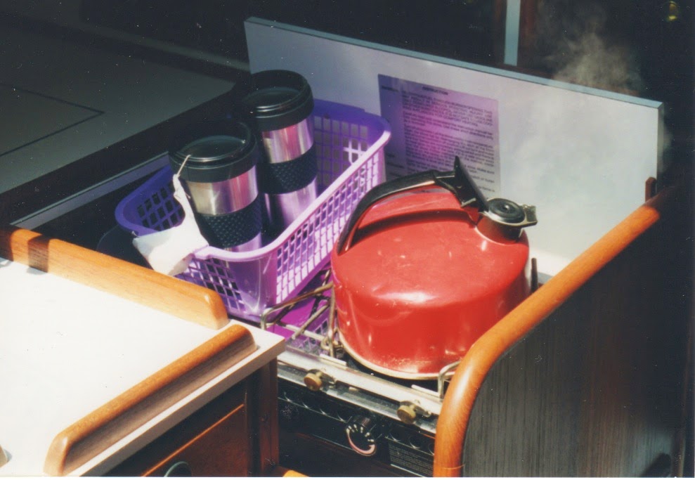
This photo shows the finished installation during use and underway. Time for tea!


{Lessons learned:
1. Athwartship mounted, fixed stoves do not belong on a sail boat.
2. Be willing to sacrifice a little seating space for a functional stove compartment.
  1. Again, Consider the aesthetics and always attempt match the rest of the boat interior. This boat has mahogany stained teak which is very hard to match. We made up a bottle of our own special stain that we named “La Yu Hue” that was used for all of our projects.
  2. Always provide safe stowage of loose items, e.g, the stove cover, so that they do not become dangerous objects when the going gets rough.
5, Do not pass up an opportunity to add useful storage space.}

Emergency Tiller (April 1992)

For quite some time, we were concerned that the boat lacked an emergency tiller. With only the wheel steering with its many parts, it was like waiting for a disaster to happen.

Providing an emergency tiller was complicated by the fact the solid, stainless rudder stock had, apparently been cut off, and did not extend beyond the upper rudder bearing which was mounted to the floor of the cockpit. This meant that we had to extend the height of the rudder stock. When the boat was up in its cradle, for the winter, we removed the rudder. This required removal of the steering quadrant and having the boat high enough to drop and remove the rudder.

We purchased a 6 inch piece of 1-1/8 inch diameter stainless bar stock and had it welded to the top of the rudder stock by a certified welder. He did a very good job and the new, longer stock was aligned perfectly. We then machined a 1/4 inch key way into the stock. The rudder head and tiller jaws  are shown below. These pieces were obtained from Rig-Rite, Inc.


After this hardware was purchased, delivered and checked for fit to the rudder post, the woodworking could begin. We laminated a curved tiller from thin strips of teak. This required a jig, epoxy resin and careful clamping. After the rough tiller had set, it was shaped, by filing and sanding, into its final form. 
The tiller is attached to rudder head with a Ball-lok, quick release pin that is attached to the tiller with a short leash of stainless cable, to prevent loss. We store the tiller in the v-berth shelf. The rudder head is securely attached and always ready.

These pictures show the tiller before and after installation.


In the case of an actual steering system failure, the tiller can quickly be installed and the wheel can easily be removed and stored in one of the lockers. This provides added clearance for the tiller. The emergency tiller is 26 inches long and does not provide finger-tip control, yet the operating effort is not very high. Later, in 1995, we had the master link in the steering chain fail. We returned safely to port, using this tiller

{Lesson learned:
When buying a boat, carefully check the emergency tiller capability and assure yourself that the provisions are adequate. Don’t sail the boat unless it has an emergency steering capability.}